Back to All Training Tracks
ISO 26262:2018 Parts 1-12Functional Safety 6 Weeks (Self-paced + Guided)

ISO 26262:2018 (Ed. 2) Functional Safety Mastery

A complete deep dive into road vehicle functional safety: Item Definition, HARA, ASIL decomposition, Functional Safety Concept (FSC), Technical Safety Concept (TSC), quantitative FMEDA, FTA, and DFA.

Production Vehicle Architectural Blueprint

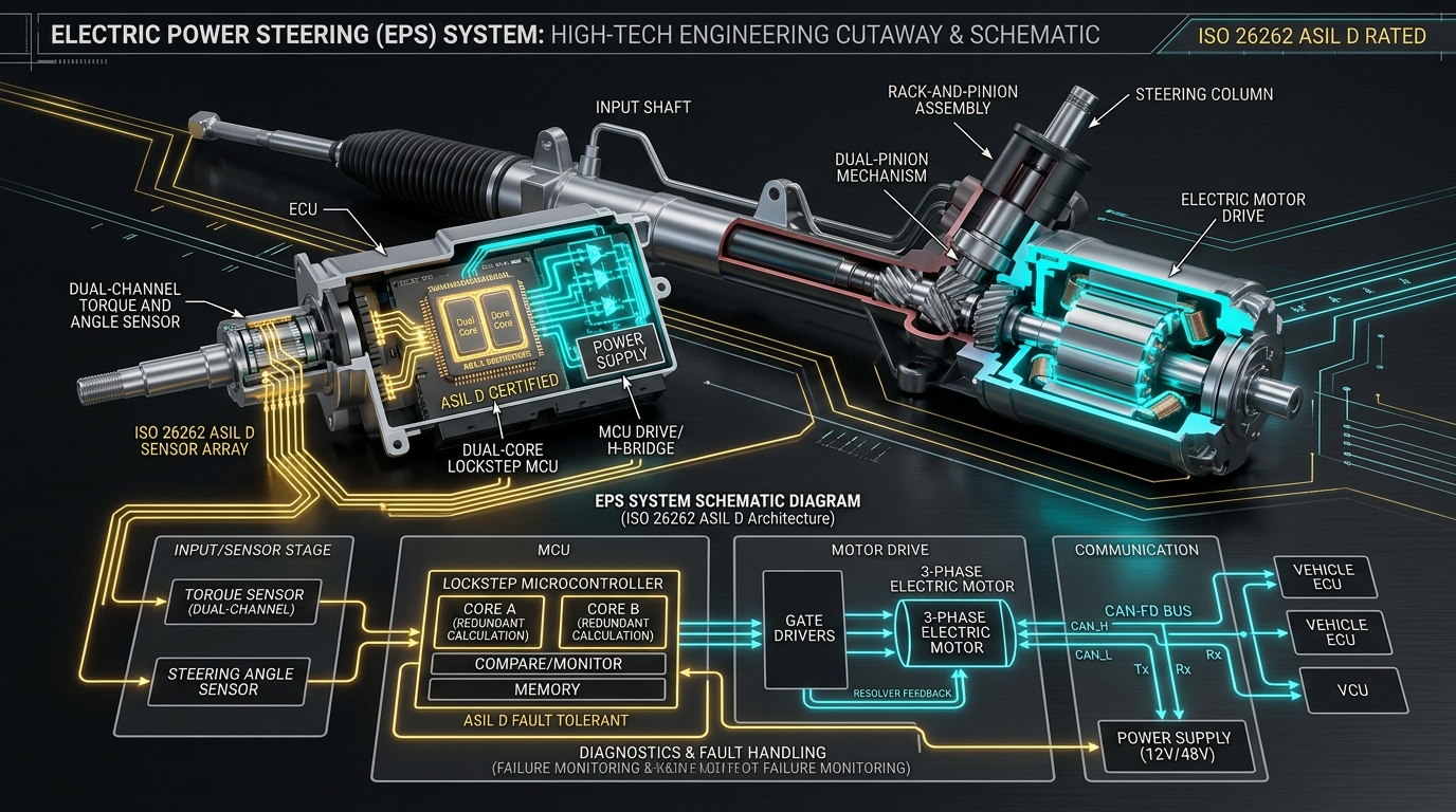
Electric Power Steering (EPS) ASIL D Architectural Blueprint

Complete mechanical rack-and-pinion cutaway, dual-channel torque/angle sensing, lockstep MCU, and 50ms FTTI fail-operational motor control.

ISO 26262 ASIL DDual-Core Lockstep50ms FTTIFail-Operational
Electric Power Steering (EPS) ASIL D Architectural Blueprint
OFFICIAL AUTOSYS TECHNICAL CAD BLUEPRINT
Hands-On Engineering Practice

Interactive Domain Laboratory & Case Studies

Complete each stage interactively with visual architectural schematics, case studies, and voice dictation.

End-to-End ISO 26262 Engineering Laboratory

The Complete Automotive Safety Lifecycle

From Item Definition through HARA, Safety Goals, Technical Concepts, Hardware FMEDA, and ASIL Decomposition. Learn through two production-grade automotive case studies with interactive schematics and voice-assisted exercises.

Target Item:
ISO 26262-3:2018 Clause 5

Step 1: Formulating the Item Definition

Work Product: 03-01 Item Definition Document

The Item Definition is the bedrock of functional safety. It establishes what is inside the system boundary, external sensor/actuator interactions, environmental operating constraints, and functional goals.

An auditor looks for 5 mandatory sections: (1) Functional Purpose, (2) Operating Modes & States, (3) System Boundary & Allocation, (4) Environmental Constraints (-40°C to +125°C, Vibration, EMI), and (5) Assumed External Driver & Vehicle Interfaces.

Electric Power Steering CAD Blueprint
HD VEHICLE CAD: ADAS ELECTRIC POWER STEERING (EPS)ASIL D TARGET
Visual CAD Inspection: Study physical sensors, mechanical column, and safety MCU packaging.ISO 26262-3 Clause 5 Item Boundary
Interactive Item Boundary Schematic: ADAS Electric Power Steering (EPS with LKA)Click any block to inspect safety role
External Inputs
Inside Item Boundary (EPS ECU)ITEM
Mechanical Actuation
Trainee Lab Exercise: Define the Item BoundarySpeak or Type your response

Question: For the ADAS Electric Power Steering system, explain why the mechanical steering rack is treated as an external vehicle element rather than inside the software item boundary, and what safe state it enables.

Lifecycle Stage 1 of 8
Interactive ISO 26262 Simulator

ASIL Derivation & FTTI Timing Verification

Adjust vehicle operating conditions to see real-time ASIL classification and fault handling timing.

1. Hazard Severity, Exposure & Controllability
Result:ASIL C
Vehicle Velocity: 120 km/hSeverity: S3
0 km/h (S0)40 km/h (S1)100 km/h (S2)180 km/h (S3 Fatal)
Operational Exposure: E3Occasional driving
E0 (Impossible)E2E4 (Frequent)
Driver Controllability: C3Difficult / <90% drivers
C0 (Easy)C1C2C3 (Uncontrollable)
2. Fault Tolerant Time Interval (FTTI)Timing Budget
FTTI Limit: 50 msHazard Manifestation Threshold
Fault Detection Time (tFD): 20 msLockstep / ADC / CRC
Fault Reaction Time (tFR): 20 msSafe State Transition
SAFE: Safe State Reached in Time

Total Handling: 40 ms | Margin: 10 ms

40 ms / 50 ms
Interactive Visual Masterclass🎙️ NotebookLM Multi-Speaker Engine● Daily Stacked Episode #1

Item Definition Mastery: Scoping the Vehicle Boundary for EPS & Inverters

Featuring Dr. Aris Thorne (Senior Safety Fellow) & Elena Vance (Principal Safety Assessor) · Added 2026-10-01 · 24 mins

Item Definition Mastery: Scoping the Vehicle Boundary for EPS & Inverters
VEHICLE CAD ARCHITECTURE
AT
Dr. Aris Thorne
Senior Safety Fellow
·
EV
Elena Vance
Principal Assessor
Dr. Aris Thorne(Senior Safety Fellow)

Elena, in over thirty OEM audits I've led, more than half of supplier safety dossiers get flagged right at Part 3 Clause 5: the Item Definition. Why do so many engineers struggle with the boundary?

Elena Vance(Principal Safety Assessor)

It comes down to scoping arrogance or scoping myopia, Aris. Too many software or hardware engineers think the 'Item' is just their microcontroller board. But under ISO 26262, the Item is defined at the vehicle function level. For an Electric Power Steering system, the item includes the sensors, the ECU, the motor, but the mechanical steering column and the driver's steering wheel are external interfaces.

Dr. Aris Thorne(Senior Safety Fellow)

Exactly. If you forget that the driver can physically overpower a minor motor fault or that a mechanical seized pinion causes a catastrophic loss of control, your entire subsequent HARA is fundamentally flawed.

Elena Vance(Principal Safety Assessor)

That's right. And when you write the functional requirements of the item, you must declare every operating state: Key-Off, Pre-Drive self-check, Assist Active, Limp-Home, and Thermal Derating. If your boundary diagram doesn't show power supply voltage fluctuations down to 6 volts during cold engine cranking, an OEM assessor will reject your item definition immediately.

Dr. Aris Thorne(Senior Safety Fellow)

Let's give our engineers the exact mission: You are tasked with drawing the boundary diagram for an 800V traction inverter. What belongs inside the boundary and what is outside?

Elena Vance(Principal Safety Assessor)

Inside the boundary: gate driver ICs, DC link capacitor, SiC power modules, phase current sensors, and safety MCU. Outside: the high-voltage battery contactors, vehicle CAN-FD bus, and vehicle cooling loop. Understand that boundary, and you will pass your audit with flying colors.

Line 1 of 617% Complete
Item Definition Mastery: Scoping the Vehicle Boundary for EPS & Inverters

A deep conversational breakdown between senior safety fellows on how to define the item boundary, capture external mechanical interfaces, and avoid the most common audit rejection traps.

Stacked Masterclass Series (5)Daily Cadence
Hardware & Software Interfaces
Mechanical Rack Assembly
Direct linkage providing driver manual fallback torque if electrical assist collapses.
Dual-Channel Sensor
Provides independent analog and digital angle/torque signals with cross-plausibility.
Lockstep Core MCU
Hardware comparator running redundant torque math with 1-cycle execution delay.
Phase Disconnect FETs
Allows instant motor decoupling to prevent uncommanded mechanical steering lockup.
Independent Engineering Takeaways
  • Why mechanical steering racks are external interfaces to the EPS item
  • Drafting ironclad functional interface matrices across CAN-FD and power rails
  • Distinguishing item functional dependencies from environmental stress boundaries
Detailed Knowledge Repository

Engineering Curriculum & Standards Guidance

1. Item Definition & Boundary Formulation (Part 3, Clause 5)

Scoping the system boundary, environmental interactions, and operational modes

The Item Definition is the foundation of functional safety. It establishes what is inside the item boundary, its dependencies (actuators, sensors, communication buses), driver interfaces, and legal requirements.

Common trap in OEM audits: Defining the item too narrowly (e.g. only the microcontroller) or omitting environmental boundary conditions (e.g. high-voltage DC bus ripple, thermal extremes from -40°C to +125°C).

You will learn to write an ironclad Item Definition with interface matrices, operating modes (Run, Sleep, Limp-Home, Charging), and vehicle-level interactions.

Core Architectural Takeaways

  • Must define vehicle-level functionality, not just ECU internal behavior.
  • Identify all non-functional requirements including ambient operating conditions.
  • Document all assumed external measures and driver interfaces.

OEM & Tier-1 Technical Interview Guidance

Interview Question: What is the difference between an 'Item' and an 'Element' in ISO 26262?

Winning Answer: An Item is a system or combination of systems at the vehicle level that implements a function. An Element is a constituent part of an item (subsystem, hardware component, or software unit).

2. HARA & ASIL Derivation (Part 3, Clause 6)

Severity (S), Exposure (E), Controllability (C) -> ASIL A, B, C, D

Hazard Analysis and Risk Assessment (HARA) evaluates unintended vehicle behaviors under all operational situations without considering safety mechanisms.

Severity (S0-S3): Evaluates potential injury severity to vehicle occupants and vulnerable road users.

Exposure (E0-E4): Quantifies how often the vehicle enters the operational driving scenario.

Controllability (C0-C3): Assesses the percentage of drivers capable of avoiding harm when the malfunction occurs.

Safety Goals (SG) are formulated as top-level safety requirements specifying the Fault Tolerant Time Interval (FTTI) and Safe State.

Core Architectural Takeaways

  • HARA must evaluate the vehicle in the absence of internal safety mechanisms.
  • FTTI defines the maximum tolerable delay before a fault causes a hazardous event.
  • ASIL D requires the most stringent development rigor, independent verification, and lowest hardware failure rates.

OEM & Tier-1 Technical Interview Guidance

Interview Question: How do you determine FTTI for an Electric Power Steering (EPS) system?

Winning Answer: By calculating the lateral deviation rate of the vehicle on a high-speed curve under unintended maximum torque steer before the vehicle leaves its lane. For EPS, FTTI is typically 30-50 ms.

3. Hardware Architectural Metrics (Part 5: FMEDA & SPFM)

Single-Point Fault Metric (SPFM), Latent Fault Metric (LFM), and PMHF calculation

ISO 26262 Part 5 requires mathematical proof that random hardware failures will not breach safety goals.

Single-Point Fault Metric (SPFM): Measures robustness against single faults. Target for ASIL B is >=90%, ASIL C >=97%, ASIL D >=99%.

Latent Fault Metric (LFM): Measures robustness against multiple-point faults where the first fault is hidden. Target for ASIL B/C is >=60%, ASIL D >=90%.

Probabilistic Metric for random Hardware Failures (PMHF): Target for ASIL D is < 10 FIT (10^-8 failures/hour).

Core Architectural Takeaways

  • Diagnostic Coverage (DC) directly determines whether dangerous faults are detected.
  • Hardware lockstep CPUs, ECC on SRAM/Flash, and windowed voltage monitors provide the 99% DC needed for ASIL D.

OEM & Tier-1 Technical Interview Guidance

Interview Question: If your micro has an SPFM of 96.5%, can it be certified for ASIL D?

Winning Answer: Not alone, because ASIL D requires SPFM >= 99%. You must introduce external diagnostic mechanisms, such as an independent safety PMIC watchdog or redundant sensing with cross-plausibility.

AutoSys Professional Certification

Earn Your Accredited Automotive Credential

Register for a free learner account to save your lab progress, unlock downloadable templates (HARA Excel sheets, FMEDA calculators, GSN safety case templates), and earn your verified completion certificate.